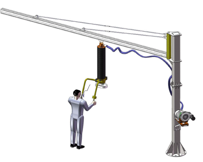
ESL Manual for Vacuum tube lifter(2019)
Keyword:Vacuum tube lifter Time:2020-2-17 15:55:47
ESL Vacuum tube lifting device
Handling with easy
User Manual for ESL
______________________________________________________________________________________________________
Carefully read before use!

1. Sphere of application and proper utilization
2. Safety
2.1 Guidelines for the user company
2.2 Guidelines for the installation, maintenance and operating staff
2.3 Safety guidelines in these operating instructions
2.4 Requirements for the installation site
2.5 Proper utilization
2.6 Emissions
2.7 Special risks
2.8 Workplace
2.9 Guidelines for the user
2.10 Personal protective clothing
3. Technical data
Types of suction pads
4. Construction and functional description
4.1 Vacuum generator
4.2 Lift unit (without control unit)
4.3 Control unit
4.4 Suction pads
4.5 Accessories
5. Installation
5.1 Installation procedures
5.2 Set suspension state (without load)
5.3 Set suspension state with load( for rocker lever control unit only)
6. Operation
6.1 Additional safety instructions
6.2 Raising, lowering and setting down loads
6.3 Changing the suction pads
7. Faults
8. Maintenance
8.1 Cleaning
8.2 Checking the sealing
8.3 Vacuum generator
8.4 Dust filter
8.5 Maintenance and inspection list
9. Dust filter
9.1 Proper utilization
9.2 Installing the filter
9.3 Attaching the holder
9.4 Insert filter in holder
9.5 Maintenance and repair
9.6 Taking out the main filter element
9.7 Spare parts
10. Vacuum Blower
10.1 Safety and application
10.2 Start-Up
10.3 Electrical Connection
10.4 Operation instructions
10.5 Maintenance
10.6 Spare part
11. Turning Head
12. Control unit
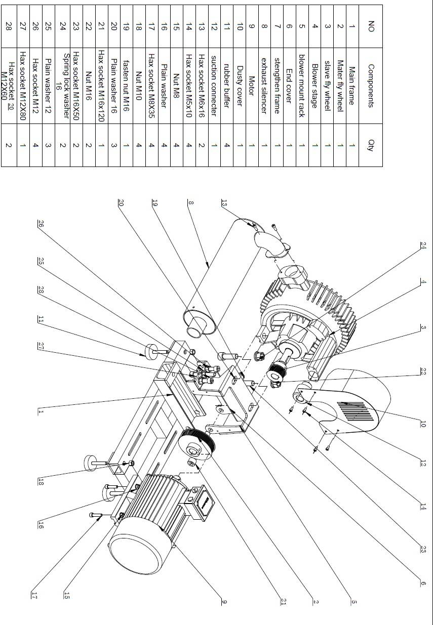
13 Vacuum blower explosion drawing:
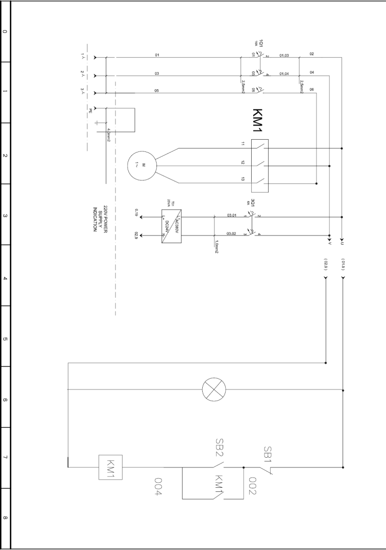
14. Electric circle drawing:
Dear Customer,
Thank you for your confidence in our Vacuum tube lifter. We hope that your new system will give you many years of good service. To guarantee the reliable functioning of your new system, you should adhere strictly to the guidelines and instructions given in these operating instructions and your system should be serviced at regular intervals. This includes ensuring that this information is read, understood and adhered to in every detail by those working with the system.
The complete operating instructions should always be stored in the vicinity of the system.
We cannot be held liable for any damage and operating faults resulting from non-adherence to these operating instructions!
We reserve the right to make technical changes to improve the system, in deviation from the diagrams and information given in these operating instructions!
If you should experience any problems, please contact us. We should be pleased to be of assistance to you at any time:
The copyright to these operating instructions of Vacuum tube lifter is held by us, These operating instructions are intended for the operating and supervisory staff. The contain instructions and diagrams of a technical nature that should not be distributed, either in part or as a whole, nor should they be used for the purposes of creating unauthorized competition or made known to third parties.
1. Sphere of application and proper utilization
The hose lift models ESL 100, 120, 140, 160, 180, 200, 230,275,305 are used to lift and transport objects, taking into account the maximum carrying capacity as stated (see carrying capacity information and guidelines on the drawing and in the appendix to the operating instructions and labels on the system).
• Any changes to and conversions of the system are prohibited!
• The devices are intended for use indoors spaces.
• Any additional form of utilization shall be deemed to be improper. The manufacturer cannot be held liable for any damage resulting from this. The risk shall be borne entirely by the user.
2. Safety
2.1 Guidelines for the user company
The ESL lifting device has been constructed using state-of-the-art technology and safety standards. However, it may be dangerous:
• If not used by trained or at least by persons who have received instructions,
• If used for a purpose for which it has not been intended.
Utilization under these circumstances may result in endanger of:
• Life and health of the users or third persons.
• The lifting device and other property of the user.
2.2 Guidelines for the installation, maintenance and operating staff
The device may only be installed and serviced by qualified technical staff, mechanics and electricians. Any person at the user‘s company entrusted with the installation, initial operation, servicing and repair of the device, must have read and fully understood the operating instructions, especially the chapters on “Safety” and “Operation”.
• The company of the operator has to ensure through in-house measures that,
• That the operating instructions have been read and understood.
• That the operating instructions are available all time.
• Responsibilities for the different activities on the unit must be stipulated and adhered to.
2.3 Safety guidelines in these operating instructions
The safety instructions in these operating instructions are labeled as follows:

The warning mark indicated an immediate danger. This may result in death or serious injury if preventive steps are not taken,

The warning mark indicated a potentially dangerous situation. This may result in slight or minor injuries if preventive steps are not taken,
2.4 Requirements for the installation site
The ESL Vacuum tube lifter may not be normally operated in the rooms where there is a risk of explosions. However, an explosion-protected version can be supplied on request.
Please give the necessary instructions to ensure that the work environment is always clean and easy to monitor. If the material to be transported or the environment were dusty, a dust filter must be used on the suction side of the fan and the dig filter on request may be needed to prolong the working time
2.5 Proper utilization
The ESL is used for lifting and transporting all kinds of objects. The permissible carrying load would not be exceeded.
Please see the type label!
The transport of people or animals using this lifting device is prohibited!
For safety reasons, any conversion or adaptation of the lifting device is prohibited!
2.6 Emissions
The continuous sound level is <80 dB (A).
2.7 Special risks
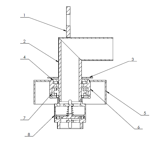
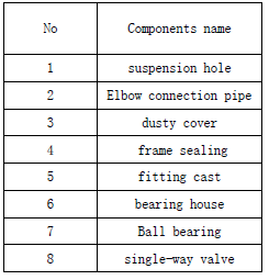
As the load adheres to the suction pads of the device under vacuum, it will fall off as soon as this pressure cannot be maintained. This will happen in the event of a sudden power failure. An integrated single-way valve in the rotation head inlet ensures the delayed fall time.

In case of a power failure, try to set down the load immediately. If this is not possible, move out of the danger zone immediately.
2.8 Workplace
The operator‘s workplace is in front of the control unit.
 Ensure that nobody switch the lifting device on or off without authorization, eg. Never leave the key in the ignition for preventing unauthorized operation to main switch.
Never stand below the load!
2.9 Guidelines for the user
As a user, you must carefully read the manual before the initial operation of the lifting device. You must have fully understood the operating instructions, especially the chapters on "Safety" and "Operation". Please ensure that only authorized persons premised to operate with the device. Within the operating range of the device, you are responsible for third parties.
The safety regulations, including UVV18.2/ VBG9 „Cranes“ and UVV18.4/
VBG9a „Load-lifting devices...“.Any additional safety instructions given here do not replace the above mentioned safety regulations, but should be regarded as additional.
2.10 Personal protective clothing
When operating the device, always wear safety shoes. Suitable safety clothing must be worn when transporting dangerous goods.
3. Technical data
For technical data, see type labels resp. separate operating instructions in the Appendix
Types of suction pads
The suction pads are designed in accordance with the material to be transported by the customer. If other optional suction pads are used, this should be coordinated with us, otherwise the company can accept no liability with regard to operation safety.
The following types of suction pads are used:
Suction head Pads designation
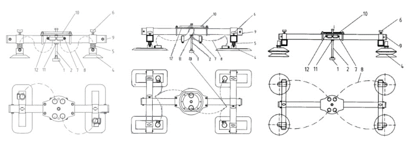
Single suction pad Round suction pad, Rectangle suction pad, For-sack suction pad
Double suction pads SPD-85*200, SPD-120*320, SPD-140*380
Multiple suction pads HB120, HB150, SPM-85*200, SPM 120*320
4. Construction and functional description
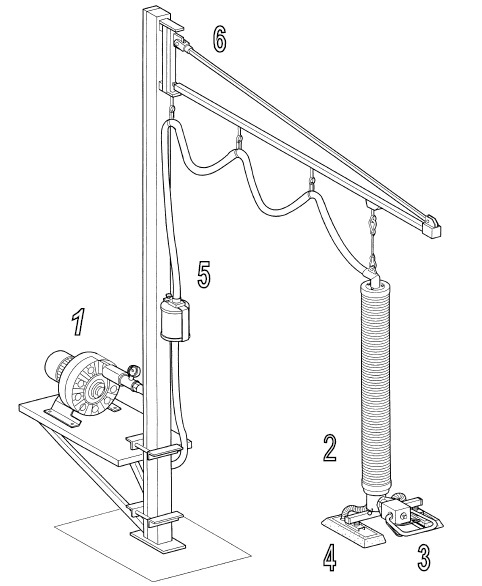
1. Vacuum generator
• Vacuum blower
• Vacuum pump
• Vacuum Ejector
2. Lift unit without control unit
• Rotation head
• Lift tube
3. Control unit
• With rocker lever
• With turning handle
4. Suction pads
• Individual suction pads
• Double suction pads
• Multiple suction pads
5. Accessory parts
• Feeding hoses and filters
• Adaption options
6. Crane systems
• Wall-mounted jib cranes
• Column-stand jib cranes
• Bridge suspensions systems
4.1 Vacuum generator
The vacuum generator could be vacuum blower, vacuum pump or vacuum ejector. It generates the necessary vacuum for “gripping” and “Lifting” the load. It can either mounted separately on the floor or on a rack attached on the column of jib crane. In addition, the vacuum blower could be equipped with an additional sound absorber on the exhaust side.
4.2 Lift unit (without control unit)
Rotation head
The rotation head is the link between the feeding hose and the lift tube. It has an integrated single-way valve to provide keeping time to the load in the case of power lost of the vacuum generator. The turning head also worked as a hook point for the tube lifter from the crane.
Lifting tube
The lifting tube leads the vacuum to the suction pads and makes the lifting movement of “up-down” possible.
4.3 Control unit
• Control unit with rocker lever
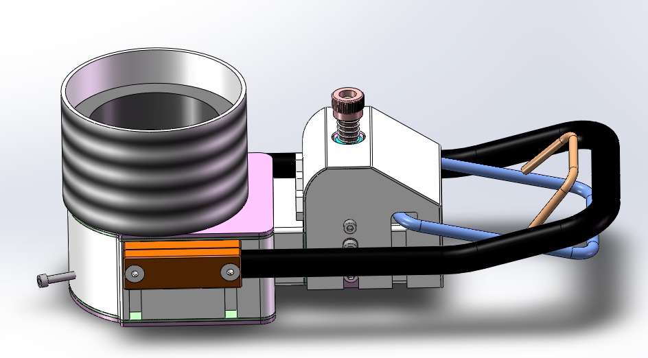
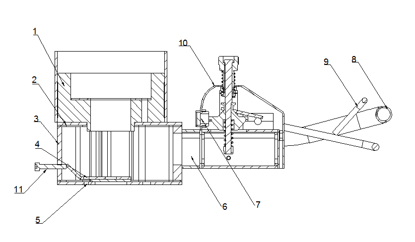
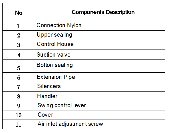
The control unit is used to control the functions for “gripping”, “lifting”, “lower” and “separation” with load. A rocker lever is used to switch between the functions. Depending on the position of the lever, a predefined vacuum is generated in the lifting tube. If the rocker lever is at the very top (on block), the load is lifted. If it is at the very bottom, it is on “Aerate” (the load is released by the suction foot). There are various height levels between these two positions
• Control unit with rotation handle
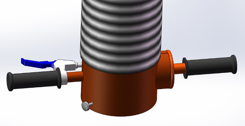
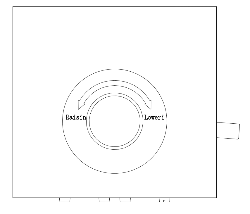
The right hand rotation control unit is used to control the functions for “gripping”, “lifting” and “lower” with load, the left hand “Brake lever” is used to separated the load from suction pads, the rotation handle makes it possible with holding the load position by rotation degree. Depending on its position, a predefined vacuum is generated in the lifting tube, and the load would be stay at appointed height. The load would never suddenly fall from the suction pads unless the left-hand brake lever is pressed
4.4 Suction pads
Check the feeder hoses and the lift hose for density(no leaks, cracks, holes, loose hose clamps)
Check the suction foot connection
Clean resp. exchange the filter cartridge
Use a higher-powered vacuum generator
Use another suction foot if necessary
Fit a new feeding hose
Fit a new lifting tube
Check the rubber seal on the strainer and exchange if Necessary
Check the rubber seal on the control house and change if necessary
Increase the air flow by turning the unload balance adjustment screw on the control house
Increase the air flow by turning the unload balance adjustment screw on the control house
See Chapter of setting the state of suspension Without load to be handled
Clean or change the dust filter

Round pads Rectangle pad Bellows pad

For-sack suction pad-1 For-sack suction pad-2
Double suction pads Multiple suction pads
4.5 Accessories
They must be regarded in accordance with their functions.
5. Installation
5.1 Installation procedures
The device may only be serviced by qualified specialized staff, mechanics and electricians.
Setting up the vacuum generator:
1) Set up the vacuum generator on rubber-buffer in a suitable location. If the vacuum generator need to be mounted on the jib crane, a shelf was optional for column installation.
2) The exhaust air of the vacuum generator must not be block existed for air flow
3) There should be at least a 2-meter distance to the next fixed object.
4) The feeding pipe is to be connected to the suction inlet of the blower and secured with a hose clamp. The other side of the feeding pipe is to be attached to the turning inlet or to the optimal dust filter.
5) The electrical connection must be in accordance with the VDE guidelines. The voltage stated on the vacuum generator type label must be strictly complied. Ensure that there is overload protection valve mounted on the feeding pipe for blower protection
Vacuum generator running test:
When initially operating the vacuum generator, the direction of flow must be checked in accordance with the arrow on the blowers or pumps.
1) Switch on blowers or pumps
2) Air must flow out of the exhaust. If this is not the case, the electrical connection is faulty.
3) Reverse connection poles.
4) Check again
5.2 Set suspension state (without load)
To ensure that the operating unit (control house, control lever, suction pads) always stays at certain height when operated without load, an adjustable pressure valve is used for air flow control that enter the lifting tube from the suction pads, the valve has been integrated into the control house. This may be regulated via an adjusting screw attached to the side of the control house (Pos1)
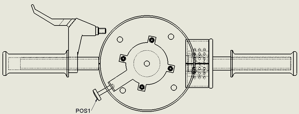

The operator must ensure that there is enough air flow to grip the loads while the rotation handle control unit was used, low air flow might cause the loads fall down suddenly! This is the prerequisite for the lifter adjustment.
Turn lower adjusting screw Raise/lower to suspension height
Turning the adjusting screw in a clockwise → operating unit lowered
Turning the adjusting screw in a anticlockwise → operating unit raised

The pressure valve should never be completely closed, as there is a risk of its “rapidly snapping back”!
5.3 Set suspension state with load( for rocker lever control unit only)
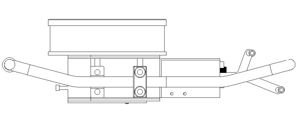
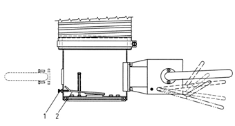
To ensure that the operating unit (control house, control box casing, suction) always stay at a certain height when operated with load, an adjustable pressure valve is used (Pos. 2 diagram below), which has been integrated in the control box casing. This can be regulated by using an adjusting screw (Pos. 3).
Turn adjusting screw Raise/lower to suspension height
Turning the adjusting screw in a clockwise → operating unit lowered
Turning the adjusting screw in a anticlockwise → operating unit raised
6. Operation
6.1 Additional safety instructions
Always wear safety shoes and protection glasses during working
Wear suitable protective clothing when hazardous goods have to be handled.
Do not exceed the maximum carrying capacity of the device.
Never stand below the load being lifted. Do not transport loads above people.
Never transport live animals!
Exercise caution with regard to other people around the workspace.
Never put the suction pads on the floor, work loads etc while off duty, which may lead to uncontrolled rapid “jumping” of the load, for example, against with the floor might cause the vacuum blower overheat
Do not release the handle as long as the load is being lifted.
Do not pull the work load or drag it form side.
Do not use the lifting device to pull loose loads which might lead to pipe or filter jammed.
In case of power failure, switch the rocker lever to “lift” position immediately (the rotation lever control unit was by turning the lever at anticlockwise), so that the load would not fall down. The residual vacuum in the lifting tube will then ensure that the hose lift and the transported material sink slowly to the ground.
Only suck and lift materials suitable for handling (check for internal stability and porosity).
6.2 Raising, lowering and setting down loads
The following operating steps must be checked by a qualified mechanic before initial operation and operated by the fully trained staff. Any defects encountered must be completely eliminated before work begins.

• Lifting:
1) Position the suction pads directly above the load.
2) Push the control clamp upwards for rocker lever control unit (the rotation lever control unit was by turning the lever at clockwise). The vacuum lifting tube starts loosen and the suction pads moves downwards.
3) Place suction pads onto the load. Ensure that the load is evenly distributed and all suction pads were not exceeded the load surface..
4) Slowly pull the regulation lever upwards (the rotation lever control unit was by turning the lever at anticlockwise). Suction is applied to the load.
5) Set the desired state of suspension for the load by turning the adjusting screw (for rocker lever control unit only), please be attention: do not confuse with the state of suspension without load).
6) If you turn the adjusting screw in a clockwise direction, the state of suspension with the load is raised, while turning the adjusting screw in an anti-clockwise direction results in a lower state of suspension(for rocker lever control unit only).
• Lowering, setting down:
1) Slowly move the regulation lever downwards “Lowering” (the rotation lever control unit was by turning the lever at clockwise). The vacuum lifting tube will be loosened and the suction grip will lower the load. 

Do not abruptly push the regulation lever downwards all the way. The load could suddenly drop, as the vacuum is eliminated entirely.
Warning! Never press the “brake-like” loosen lever on left hand before the load set down and fully placed, that would lead to the load suddenly fall down and cause harmful injuries to people or damage to property
2) Set down the load where desired.
3) To “Loosen” the load, push the rocker lever all the way down, slightly tip the control unit and lift.( for the rotation levered control unit, press the “brake-like” loosen lever, and then turning the rotation lever at anticlockwise)
Rocker levered control unit Rotation levered control unit
6.3 Changing the suction pads
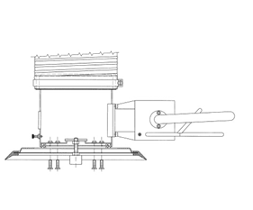
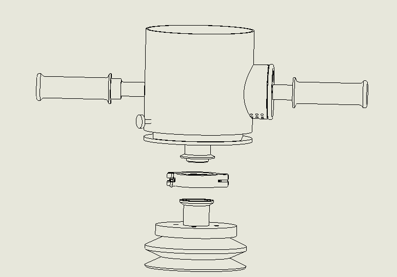
The suction feet may be exchanged, depending on the application. On the one hand, they may be directly screwed onto he suction pads. They can also be in a quick-change chunk. The suction feet must be attached to the control house, using the screws and the intermediate seals, as shown in Diagram bellow
Screwed connection Quick-change chunk
7. Faults
The ESL may only be installed and maintained by qualified mechanics and electricians.
After repair or maintenance work, always check the safety devices as described in the chapter on “Safety”. If the load cannot be lifted, check the following list to find and eliminate the problems:
| Fault | Remedial measures |
| The vacuum blowers aired from the suction connection | Reverse the poles of the fan connection phases |
The vacuum is not strong enough | |
The load is too porous or bends too much | |
The feeding hoses have cracks, holes, etc. Suction grip is not tight | |
The load falls off when lowered | |
The vacuum is attained, but cannot lift porous loads | |
The lifting tube always goes up to its upper limit position |
8.1 Cleaning
The maintenance procedures and the corresponding maintenance intervals may be taken from our service table
Dirt should be removed from the suction foot at least once a week. Use a cold cleaner (no corrosive liquids. Broken or worn suction pads should be changed immediately while found. The feeding hose and the lifting tube should only be cleaned with cold cleaner or soap suds.
8.2 Checking the sealing
Schedule a routine inspection for suction pads wear and tear was needed, as well as firm fit and leak-tightness, change if necessary.
8.3 Vacuum generator
The vacuum pump or vacuum blower may not be opened during the warranty period. Any unauthorized disassembly of the vacuum generator will result in the termination of the guarantee! Maintain the pumps or blowers according to the operating instructions provided
8.4 Dust filter
See separate operating instructions for maintenance of the optional dust filter.
8.5 Maintenance and inspection list
Frequency | daily | weekly | monthly | yearly | Annually test | |
Vacuum generator | ||||||
Does the vacuum fan run properly(no unusual noise) | ◆ |
|
|
| ◆ | |
Check blower belt tension and adjust if necessary |
|
|
| ◆ | ◆ | |
Check the filter clean |
| ◆ |
|
| ◆ | |
Check the electric cable connections in its order |
|
|
|
| ◆ | |
Check the feeding hose in its order |
|
| ◆ |
| ◆ | |
Clean or replace sound absorber |
|
|
| ◆ | ◆ | |
Check the overheated valve effective while dense work load applied |
| ◆ |
|
| ◆ | |
Lifting assembly with control unit | ||||||
Check the lifting tube conditions (no cracks, slits, holes, etc.) |
|
| ◆ |
| ◆ | |
Check tube clamps in firmly fitted? |
|
|
|
| ◆ | |
Check the turning head with easy rotating |
|
| ◆ |
| ◆ | |
Tension strap attachment and seal on lift hose in order |
|
|
| ◆ | ◆ | |
Check the operation instruction labels and rated loads labels in its original set place |
|
|
|
| ◆ | |
Are there still operation manual easy to obtain and are they known to the workers? |
|
|
|
| ◆ | |
Check the handle or control lever clamp firmly attached |
|
|
|
| ◆ | |
Check the operation unit still have a filter mat and has it been cleaned |
|
| ◆ |
| ◆ | |
Suction pads | ||||||
Check the suction pads sealing (no cracks, sealing lip worn, etc.) |
| ◆ |
|
| ◆ | |
Check the distribution hose in its order and all connection clamps firmly screwed, as well as inspection for leakage-tight |
|
| ◆ |
| ◆ | |
Functions | ||||||
Check the unloads suspension state |
|
| ◆ |
| ◆ | |
Check the Single-way valve effective in case power lost |
|
| ◆ |
| ◆ | |
9.1 Proper utilization
The dust filter may only be used when in a flawless condition! In particular, flaws that could adversely affect the safety should be promptly eliminated! The dust filter is only intended for the mechanical filtering of air. Its components are as follow:

9.2 Installing the filter
The dust filter may be mounted either vertically or horizontaly. In the case of vertical installation, the lower casing must be at the bottom. Wrong installation directions will result in the termination of the warranty for the dust filter and the vacuum generator.
• The temperature resistance of the dust filter ranges from –40°C to +80°C in the case of continuous operation, or up to +100°C for short-term operation(within 30 seconds)
• The air suction point should be in a more or less dust-free environment.
• Safeguard against water.
• The sucking of hot air should be avoided.
• The arrow “Top” should always point upwards when the filter has been horizontally installed.
9.3 Attaching the holder
The holder is attached with M8 screws (screw torque 25 Nm)
9.4 Insert filter in holder
1. Insert the filter in the holder and turn/push it into the desired position, taking care that the filter clicks into the holder.
2. Close the clamp and lock it. If the filter is fitted horizontally, it should be taken that the “top” label is at the top; if this is not the case, remove the lower casing, turn and refit.
9.5 Maintenance and repair
Cleaning, maintenance and repair work should only be undertaken when the vacuum generator (motor, compressor, blower, etc.) is switched off. Do not start if the filter element has been removed.

9.6 Taking out the main filter element
The main filter element should never be washed or brushed. When blowing out the dirt, no dust may reach the inside of the main filter element
9.7 Spare parts
Content | Type | Art No |
Spare filter insert (plastic filter) | FPI-50 | 4.50.230.01 |
Spare filter insert (Metal filter) | MTI-30 | 4.30.120.01 |
10. Vacuum Blower
10.1 Safety and application
The vacuum blowers are designed based on applied requirement with safety regulations complied. Still, If not installed properly or not used as directed, dangerous situations or damage might occur. In this operation instruction of vacuum tube lifter, safety measurements are complied before each step. It is imperative that these safety precautions are observed.
Application
The blower can be used wherever air is to be sucked. Besides air, any non-aggressive and non-explosive gases and gas mixtures can be transported. The gas temperature should not exceed 40°C.

Liquids and solid particles enter the blower were completely prohibited, which would cause the blow vane stuck and overheat to burn
10.2 Start-Up
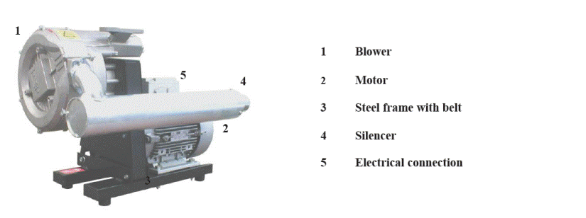
It is essential to observe the following instructions step by step to ensure a safe start up. Start up may only be conducted by trained specialists.
1) Mounting
The frame with the mounted blower stage and motor must be located only in horizontal position. The mounted rubber buffers must be adjusted in order to ensure a safe position of the frame. The blower can be located directly on the floor or on a mounting plate with corresponding connection bores.
2) Suction connection
The connection of the suction flange can be effected through a vacuum flexible hose or through a tube line.
- Please note:
Any strain of connections onto the blower must be avoided.
The pipe size should never be smaller than the size of the blower inlet and outlet connections. Reductions of the pipe size may cause a loss of vacuum. Before start-up, make sure that no foreign bodies (e.g. Welding tinder) are in the inlet or outlet pipes.
Technical data for the motor and the blower can be found on the nameplate.
It is important that a free flow of air around the blower is maintained so that the efficiency of the cooling fan is not impaired.
Ambient temperatures should not exceed 30°C. The silencer exhaust must not be located closed to objects or walls.
10.3 Electrical Connection

The operator of the blower has to inform the manufacturer if expected electric or electromagnetic interference may exist in working areas
Voltage and frequency on the nameplate must be consistent with the supplied power
The drive motor must be protected by a safety switch, compatible to the motor current. On portable equipment suitable connections should be made so that the wiring and starter cannot be damaged.
To check the direction of the rotation of the blower, flick the ON/OFF switch. Reverse the polarity of any two of the electrical phases in case of incorrect direction

10.4 Operation instructions

Not to be used with aggressive and explosive gases or gas mixtures and fluids
Excessively high pressure may cause failure of the blower
 The blowers do not require maintenance lubrication
Solid or liquid particles must not enter the blower at any time. In case of contaminated air may be expected, an inlet filter should be installed.
The blower should not run for longer periods of time with either a closed inlet or outlet. In this Case, the tolerable holding time should be within 1 minute.
10.5 Maintenance

Be sure that vacuum pump is switched off before starting maintenance, and confirmed the safe the unit against unintentional restarting.
The blowers require no routine maintenance apart from regular cleaning of the inlet filter (accessory).
The operating temperature should be checked regularly. It must not exceed 100°C in an ambient temperature to 30°C.
Please check the drive-belt regarding signs of wear on a regular basis. The drive-belt will be adjusted manually by screws. Please change the drive-belt if you realize some wear on the drive-belt. For the change, you have to loosen the fasten screw and lower the blower frame from complete frame until the belt droop, then take out the drive-belt.
A spare drive-belt was in plastic bags as consumable with vacuum lifter.
10.6 Spare part:
Content | Type | Art-no |
Driven belt | PG-220 | 3.25.220.01 |
11. Turning Head
12. Control unit
Rocker levered control unit:
Rotated lever control unit:
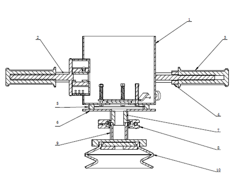
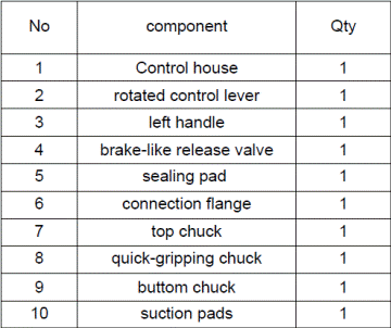
13. Vacuum blower explosion drawing:
14. Electric circle drawing:
