Installation guide for Jib crane of vacuum tube lifter(悬臂吊安装指导作业书)
Keyword:Jib crane installation Time:2020-11-2 13:43:23
Installation guide for Jib crane of vacuum tube lifter
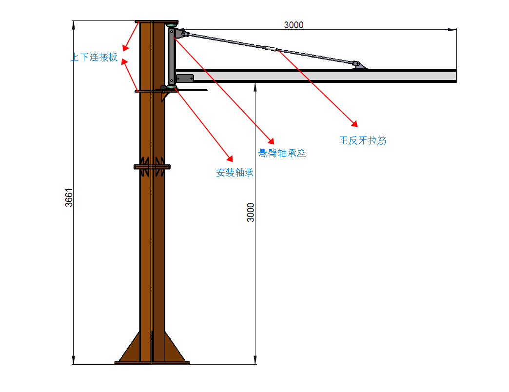
Y Composition diagram of Jib crane

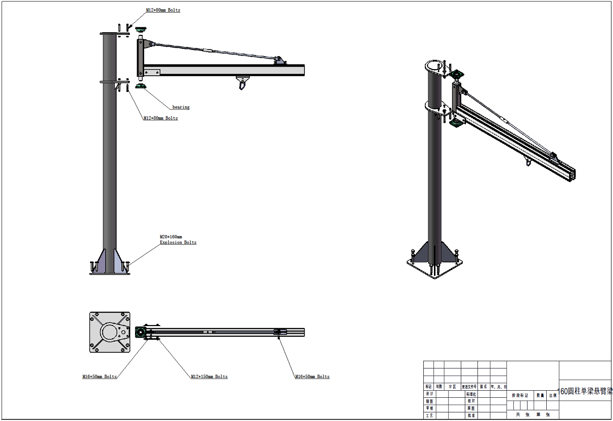
The jib crane is made up of base plate, pillar, fixing system, rotation bearing, Swivel bearing bracket, Diagonal reinforcement and jib (cantilever) etc
Prework before installation
Check the needed parts
Expansion bolt or chemical bolts on the base plate
Fixed screw for the bearing
Up and down rotation bearing
Rotation smooth shaft
Diagonal steel bar with positive and negative teeth
Mounting plate of jib
Mounting washer of base plate

Tools required and auxiliary facility for installation
1. Tools: Big adjustable wrench, Allen wrench, hammer, percussion drill, drilling bit, level bar or level gauge.
Auxiliary facility: forklift, scaffold or platform truck etc.
2. Exam the installation condition of site
Whether the height from ceiling to ground reaches the request
Whether there is obstacle above the jib, whether there is collision for jib swing
Whether there is potential obstacle in the covering area of Jib
Make sure the thickness of concrete is not less than 200mm
Make sure there is power supply on site
Make sure whether there is compressed air on site.
3. Installers and safety measures
Warning board and warning signal in installation area is a must.
Must wear safety helmet in the process of installation
Must wear goggles and Protective earplugs in the process of installation
Must wear protective mask in the process of installation
Must wear work shoes protected with steel plate
The clothing of the installer must be fitted, free of involvement, no drooping or floating ribbons, etc
Must wear saftey belt which is fixed in the safe and inmovable object for aerial work
The installers must coordinate with the worker on the ground for aerial work
If welding is required on site, the Power indicateor must be installed, and the ground wire must be connected
If welding is required on site, fire protection facilities such as fire extinguishers, fire masks, etc. are required
Irrelevant personnel are prohibited from entering the installation area
4. Installation steps
With the aid of other equipment, erect the column in a vertical state
Determine the installation position of the pillar, and adjust the installation direction of the cantilever according to the visual inspection
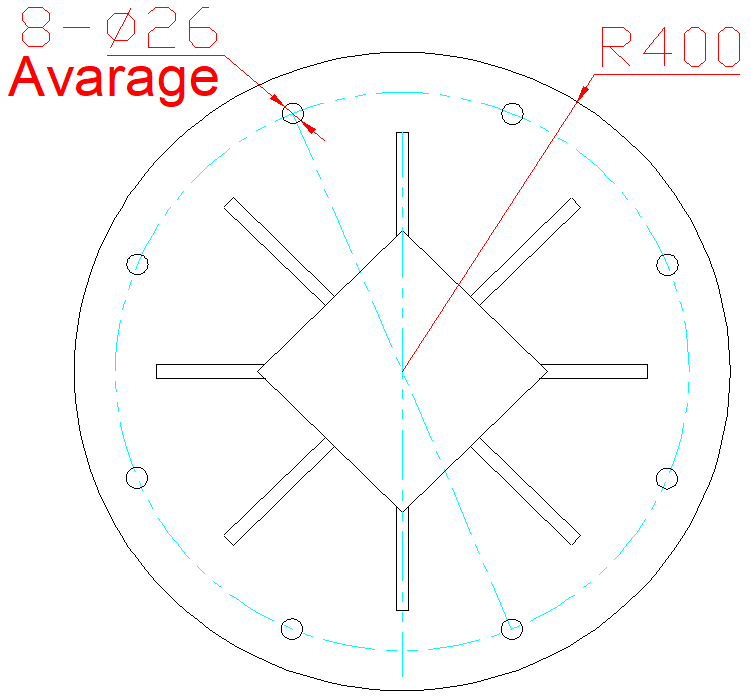
After the position is fixed, drill a deep hole with a diameter of 22mm with an impact drill according to the opening position of the base plate, and the depth should be 180-200mm
Installation diagram of base plate

FClean up the dust accumulated in the hole
FPut the expansion screw into the hole, and hammer lightly with a hammer to ensure that the expansion screw completely touches the bottom of the mounting hole
FAfter the expansion screw is in place, insert the flat washer and the spring washer into the thread in turn, screw in the nut, and tighten with a wrench
FPlace a level bar or level gauge on the pillar, add and adjust washer on the base plate according to the actual situation, until the pillar is completely level, fully tighten all the bottom plate screws, and check the level of the column again
FPut the bearing on the smooth shaft of the cantilever bearing seat. If the fit is tight, you can tap it with a hammer to ensure that the bearing will not come out.
FInstall the rotating bearing seat into the upper and lower mounting plates on the pillar, pass the mounting screws through the mounting plate, fix the bearing, the fixing screw is M12, and tighten the anti-falling screw.
FFix the diagonal brace with positive and negative teeth on the cantilever bearing seat
FInsert the aluminum profile rail into the rail mounting hole and fasten it with a splint
FFix the other end of the diagonal brace on the aluminum alloy cantilever and fasten it with screws
FPut the level bar or level gauge on the aluminum alloy track, adjust the cantilever to the horizontal position by adjusting the positive and negative teeth, and tighten all the screws.
FAfter completing the installation, reconfirm the level of the pillar and cantilever
悬臂吊安装指导作业书
Y 设备构成图:

悬臂吊是由底板,立柱,悬臂固定座,旋转轴承,旋转轴承支架,斜拉加固及悬臂等组成
Y 安装前的准备工作:
1. 检查所需附件:
包括底板安装膨胀螺丝或化学螺栓
轴承固定螺丝
上下旋转轴承
旋转光轴
带有正反牙的斜拉筋
悬臂安装板
底板安装垫片

2. 安装所需工具及辅助设施
工具:包括大活动扳手,内六角扳手,锤子,冲击钻,钻头,水平尺或水平仪
辅助设施:包括叉车,脚手架或登高车等
3. 检查现场安装条件
天花到地面的高度是否满足安装需要
悬臂上方是否有障碍物,悬臂摆动时是否可能产生碰撞
在悬臂覆盖区域是否有可能产生冲突的障碍物
确认地面混凝土厚度不小于200mm,且地面平整无坑洼及坡度
确认安装现场是否有电源,安装电源要求220V
确认安装现场是否有压缩空气
4. 安装人员及安全措施:
安装区域必须带有警示牌及警示标志,并以警示带或其他安全网进行隔离
安装人员在整个安装过程中必须全称佩戴安全帽
安装人员在安装过程中必须佩戴护目镜及防护耳塞
安装人员在安装过程中必须防护口罩
安装人员必须穿着带有钢板保护的工作鞋
安装人员服装必须合身,无牵扯,无下垂或可飘散的饰带等
安装人员在登高作业时必须佩戴安全带并固定于安全稳固的,不可移动的物体上
安装人员需配合地面工作人员指示完成登高作业
现场如果需要焊接,则必须安装安装指示接电,并保证地线连接
现场如果需要焊接,需要配备防火设施如灭火器,防火面罩等
无关人员禁止进入安装区域
5. 安装步骤:
F 通过其他设备辅助,将立柱树立为竖直状态
F 确定立柱安装位置,并根据目测调整悬臂安装安装方向
F 位置固定后,按照底板开孔位置,用冲击钻打直径22mm的深孔,深度应为180-200mm
安装底板示意图:

F 将孔内所堆积的灰尘清理干净
F 将膨胀螺丝放入孔内,并以锤子轻轻锤击,保证膨胀螺丝完全接触到安装孔底部
F 膨胀螺丝就位后,将平垫,弹簧垫依次套入螺纹,拧入螺母,并以扳手拧紧
F 将水平尺或水平仪放置于立柱上,根据实际情况在底板下增加调整垫片,直至立柱完全水平,将所有的底板螺丝完全锁紧,并再次检查立柱的水平状态
F 将轴承套入悬臂轴承座的光轴上,如配合较紧,可以用锤子轻轻敲击,保证轴承不会脱出
F 将旋转轴承座装入立柱上的上下安装板内,安装螺丝穿过安装板,将轴承固定,固定螺丝为M12,并将防脱出螺丝紧固。
F 将带有正反牙的斜拉筋固定在悬臂轴承座上,
F 将铝型材轨道插入轨道安装口,并以夹板进行紧固
F 将斜拉筋的另一端固定在铝合金悬臂上,并以螺丝紧固
F 将水平尺或水平仪放在铝合金轨道上,通过正反牙的调节,将悬臂调整至水平位置,并将所有的螺丝全部紧固一遍
F 完成安装后,再次确认立柱及悬臂的水平程度
| DOWNLOADS |


